https://www.bulksolids.nl/phenomena_in_silos.html
BSE bulk solids engineering Tel.: +31 53 434 45 66
Print: 27 Apr 2024 15:42
BSE bulk solids engineering Tel.: +31 53 434 45 66
Print: 27 Apr 2024 15:42
Phenomena in silosPressure build-up, product breakage, silo quaking, segregation
This paper discusses phenomena that can cause problems when storing bulk materials in silos. Including solution directions and some practical cases.
C O N T E N T S
Pressures in silos
Product damage due to normal, shear and impact forces
Product breakage; Calculation of silo pressure; Possibilities of pressure reduction, wall friction, silo slenderness, alternative possibilities Silo partitioning for pressure reductionLimiting pressure during storage to avoid breakage of feed pellets
Breakage of feed pellets; Determining maximum pressure; Possible solutions; Incorporating partitions, points of interest Pressure reduction using intermediate conesAvoiding shock in silos containing milk powder
Problematic loading due to shaking silos; Stick-slip behaviour milk powders; Design of intermediate cones; Intermediate cones in practice; Predictability of pressure reduction Quaking, vibrating and honking silosCauses and mechanisms
From humming to honking and quaking; Flow pattern; Causes of vibration and shock: Stick-slip, envelope mass and core flow, sliding mass, feeders, dilation; Combinations Possible solutions for shocking silosPrevention is better than cure
In the design phase; Adaptation of existing situations, Stick-slip vibrations, Resolving shocks at a boundary design, by core flow, by mass flow Pressures in silosProduct damage due to normal, shearing and impact forces
Increasing capacities or shorter lead times sometimes require larger raw material inventories.
For companies that store their raw materials in silos, this means investing in higher or wider silos.
In some cases, however, this leads to problems. This is because in a larger silo, the bulk product experiences greater pressure.
This changes its properties, and usually not for the better.
Product damage
In a production process where particles are made, e.g. animal feed pellets, it is unavoidable that some of these products break already during the process.
Besides leading to production losses and product depreciation, this can also adversely affect the processes themselves.
Product breakage
During storage, the product in a silo undergoes normal and shear forces, and possibly impact forces when the silo is filled.
The normal and impact forces can lead to breakage or fragmentation of the particles.
The shear forces cause surface damage by forming cracks or breaking out small pieces.
Damage that can occur due to impact during silo filling is not considered further here. Limiting the drop height or fitting suitable chutes reduces those problems. Calculation of silo pressure
We describe the pressure occurring in silos using the Janssen formulas. Although this method will not accurately reflect
the actual occurring pressure, the outcome does give a good indication of the pressure curve and the factors that determine pressure.
For comparing pressure levels, this is not an a problem because the pressures are always calculated with the same relative inaccuracy.
The horizontal pressure (sigmaH) can be calculated by multiplying the vertical pressure by the pressure ratio (lambda or K). The horizontal pressure in the cylinder is the same as the wall pressure, the pressure perpendicular to the wall (sigmaH = sigmaW = K * sigmaZ). The shear stress at the wall is the wall pressure multiplied by the wall friction coefficient (tau_W = sigmaW * mu_W). Influences on silo pressure
The pressure gradient therefore depends on the wall friction, but also on the ratio of surface area to circumference of the silo.
One can deduce that high pressure can occur in relatively high or wide silos and in silos with low wall friction.
The latter may be caused by the deposition of grease on wall, which is quite common in silos containing animal feed, for example soybean meal.
The standard menttions this phenomenon.
Silo pressure reduction optionsOf the factors that determine pressure according to the Janssen formulas, bulk density and pressure ratio cannot be changed much, if at all. Reducing the filling height is trivial; we leave these out of consideration. Remaining are the wall friction and the area - circumference ratio.
In cases where high pressures have undesirable consequences, one will strive to reduce pressure.
Various methods are used in practice, almost all of which affect the wall (friction).
Options for reducing pressure in silosSome options for pressure relief are:
1) Placing ringsPlacing rings in the vertical part of the silo is structurally simple. However, correct sizing is difficult. A ring that is too large can give rise (locally) to core flow, as product remains on the rings. With perishable product, this is a problem. 2) Applying rims of meshA related method is to insert strips of mesh into the cylinder. These strips are usually attached at the bottom edge. The same disadvantages apply here as with rings. An additional disadvantage is the construction itself. Due to high loads, the mesh itself may crack, or be pulled away from the wall altogether. 3) Installing dividing walls
Janssen's formula is a function of the ratio of surface area to circumference of the cylinder. Lowering this ratio will,
like increasing wall friction, lead to a reduction in silo pressure.
In fact, the ratio of surface area to circumference in a silo is nothing more than the storage volume of the cylinder
relative to the amount of silo wall with which the bulk material comes into contact.

For existing silos, one option is to increase the wall surface by installing one or more intermediate walls.
This reduces the diameter and increases the wall area. The effect of this measure is easy to calculate.
Installing intermediate walls has the added advantage of allowing different types of products to be stored.
Disadvantages lie mainly on the structural level. The wall must be solid and the silo often has to be reinforced at the attachment points.
This leads to expensive constructions. A disadvantage with regard to flow is that the opening becomes eccentric.
See the situation with feed pellets for an elaboration of
silo partitions in practise. 4) Increasing the wall friction
Increasing the wall friction coefficient leads to a substantial and almost linear reduction in silo pressure at the bottom of the cylinder.
At the top of the silo, the influence is smaller because the pressure is built up .
An example of this pressure reduction is given in the figure, where the pressure profile is shown for a fill level (Z), a silo diameter of 3 m,
a bulk density of 1000 kg/m3 and a pressure ratio of K=0.4.
It is assumed that the wall friction coefficient is increased from 0.3 to 0.6.
The figure clearly shows that the value of the vertical pressure decreases significantly especially deeper in the silo.
In the given example, it means that with the rougher wall, the same pressure is reached only at about 10 metres filling
height as with the smooth wall after about four metres. The value of the wall pressure also decreases in the same proportion.
Unfortunately, the possibility of reducing silo pressure by increasing wall friction is rather limited in practice.
This often requires some kind of coating or cladding that provides the required friction increase, is suitable for
the product concerned and is also sufficiently wear-resistant.

5) Installing insertsHang-up in silo with tie bars Inserts are flow obstructions. They can be formed by inclined plates, cones, funnels, chains, horizontal bars, etc. From practical experience, they are known to cause large pressure drop. The main advantage of inserts is that they can often be relatively small. However, here also lies the biggest disadvantage: it cannot be predicted how big the pressure drop and thus the load on the insert will be. The influence on the flow pattern is also poorly predictable. Flow problems may occur, or the product may get stuck at altitude (hang-ups). Restarting stalled flow can then be very difficult, the very reason being the built-in structures. Installing one or more so-called intermediate cones in the cylinder is then a better alternative. 
6) Using intermediate cones
With intermediate cones, the same effect occurs as with the actual cone or hopper of the silo.
The pressure in the bulk material decreases, while the load on the wall increases.
The pressure drop and the structural load are easily predictable. See the figure, which shows the pressure profile in a cylinder with an intermediate cone.
As the pressure drop is greatest at the top of the hopper, intermediate cones of limited height already result in a significant pressure drop.
In practice, an intermediate cone protruding only 3% of the diameter of the cylinder from the wall can already reduce the pressure by about half.
See the following sections for some real-life case studies on pressure reduction. Partitions for pressure reduction in siloLimiting pressure in a storage silo due to breakage of feed grainsIn the contribution above, we discussed some theoretical possibilities to reduce pressures in storage silos. This is to reduce damage to the stored product, e.g. grain breakage, or powder sticking together. This article discusses two practical examples. Livestock feed pellets in large silosAt a feed mill, animal feed pellets are produced, which are then dried and stored before being transported to customers in bulk or bagged. In the past, storage took place in relatively small storage silos. Due to production expansion, larger silos are now used. This had the disadvantage of significantly more damage to the pellets. Since the type of flow in the large and small silos was the same, mass flow in both cases, it was concluded that the cause of the increased damage was due to the higher pressure in the silos. The question then naturally arises: can anything be done about it? Starting points and possible solutionsStarting points and possible solutions
The small silo cells used previously were rectangular, with a diameter of 1.5 x 1 m, and a height of 8 m. The outlet hopper was sufficiently steep for mass flow.
The pellets had with the following properties: wall friction relative to the cylinder wall (mu_w) = 0.48; bulk weight (gamma) = 8 kN/m3.

The new silo cells were also rectangular, but now with a diameter of 2.0 x 2.8 m, and a height of 10 m. Mass flow also occurred in these silos. The vertical pressure occurring in these cells when the silo was fully filled was: sigma_z = 23.4 kN/m2, almost twice as high as before. As too many pellets broke, the pressure therefore had to be reduced. The high pressure turned out to be mainly caused by the larger cross-section. Indeed, at a filling height of 2.3 m, the pressure was already higher than at a filling height of 8 m in the old silo. Filling the silo less high with that was not an option, and undesirable anyway because of the large unused volume. Installation of partition wallsInitially, it was investigated whether pressure could be sufficiently reduced by incorporating intermediate walls, and how high these walls should be. The first situation investigated was the incorporation of a single wall, dividing the cell into two equal parts (see figure, option B). This already provides a considerable reduction of pressures in the silo, because the magnitude of pressure corresponds to the ratio of surface area divided by circumference. Nevertheless, for the current cell, the pressure reduction did not appear to be sufficient.
Therefore, the incorporation of two mutually perpendicular intermediate walls was investigated. In the event that these walls were made as high as the silo, the pressure would be well below the permissible pressure (see figure, pressure curve A). This means that the partitions need not be as high as the silo.
A modified version of the Janssen formula can be used to calculate how high the wall would have to be to arrive at exactly the desired pressure at the bottom of the silo.
In this particular case, partitions with a height of 8 m proved sufficient.
Considerations for partition wallsFor the application of partitions to reduce silo pressures, the following comments are important:
Installation of intermediate cones
The silo pressures keep increasing in the vertical section from top to bottom.
In the hopper, the pressures decrease again; the hopper walls carry very much of the total weight.
Especially the upper part of the hopper takes a lot of pressure.
This effect can be used by incorporating one or more limited-height hoppers at different heights in the cylinder.
Practical verificationTo check whether the chosen method of reducing pressure would actually lead to less product damage in practice, several tests were carried out. In one of the new cells, two mutually perpendicular partitions with a height of 7.5 m were fitted. This modified cell and the adjacent unmodified cell were then alternately filled with layers of pellets. Such that a similar product was stored in both cells. During filling, a number of samples were taken from the filling stream. After filling, both silo cells were emptied and samples were taken from the product flow at set intervals. From all these samples, the average length of the pellets was determined by counting and measuring as a comparison measure for the occurrence of the degree of product damage.
The average length of the material before the silo was 16.8 mm.
After storage in the silo cell without partitions, this length had decreased to about 12.5 mm.
At the cell with partitions, the length had reduced to about 14.4 mm.
Thus, although, as also expected, damage to the product still occurs, a significant improvement did occur by incorporating the partitions.
Pressure reduction using intermediate conesAvoiding shock in silos containing milk powderProblematic loading
At a company where milk powder is loaded in bulk trucks, they had extended the finished product silos to increase their capacity.
However, the problem after this modification was that the silos now shocked when emptied to such an extent that weighing was disrupted.
Indeed, sometimes such large shocks occurred that the silo appeared to be tons lighter. The loading was then stopped by the software, as if the target weight had been reached.
Restarting took a lot of time. To get the desired quantity into the bulk truck, loading had to be done "very carefully", which also took a lot of extra time.
Shocking, quaking silos
A literature review revealed that silo quaking can have several causes.
One well-known one is the occurrence of slip/stick (see box). Temporary bridges can also occur as a result of varying wall friction, which can cause severe shocks when collapsing.
Another cause of shocks is the reinforcement or venting behaviour of the product combined with silo geometry.
Also the change from mass to core flow in the silo, irregular outflow due to, for example, an asymmetric opening or a malfunctioning discharge mechanism can create shocks.
See causes of silo quaking.
Stick-slip behaviour
Milk powders and whey powders are known to exhibit stick-slip behaviour.
One speaks of stick-slip when a product has markedly different static and dynamic wall friction.
When measuring the wall friction of milk powder, this is clearly evident.
When the sample is stationary, the wall friction is high (stick).
Once it starts moving, the friction becomes lower so that the sample shifts quickly (slip).
The product then comes to a standstill again and the effect repeats itself.
Installation of intermediate conesIn a silo, the pressures in the vertical part increase from top to bottom. In the hopper, the pressures decrease again; the hopper walls now carry much of the total weight. It can be experienced in practice: when the outlet opening is very small, the pressures are also very low: the product can be stopped by hand, even when there is a 10-metre 'column' of product in the silo. 
The pressure drop is greatest at the top of the hopper. The solution with intermediate cones takes advantage of this. See figure above. With an intermediate cone only 25 cm high, the vertical pressure can already be reduced by a factor of 2. Design of intermediate cones
The proper functioning of intermediate cones depends on the design.
Here, the most important axes are determining the allowable pressure, and measuring the wall friction and internal friction.
Intermediate cones in practice.jpg "Silo with intermediate cones (seen towards top)")
In the situation with milk powder, one intermediate cone could reduce the pressure sufficiently, but then it had to be quite high, compared to application of two or more cones.
Moreover, the fewer intermediate cones (for the same maximum pressure level), the higher the pressure drop and thus the local load.
Predictable pressure reduction
Avoiding high product pressure is especially important for products that can cause silo quaking.
A well-known indicator of this is stick-slip behaviour, which occurs, for example, with milk powders and whey powders.
Pressure should also be limited for fragile pellets, such as pressed or extruded pellets, to prevent breakage.
With sticky and choppy products, higher pressure is detrimental because problems worsen, often more than proportionally.
Even with large mass-flow silos or silos with asymmetric flow, one must be very mindful of the adverse effects of high pressure.
Quaking, vibrating and honking silosCauses and mechanismsFrom humming to honking and quaking
Silos for storing powders or granules can generally be designed to do their job properly.
But sometimes curious and often troublesome things occur.
Some silos, in combination with certain types of bulk material, are found to produce a somewhat humming sound ('the silo sings'),
or worse, a periodic occurring sound as if a truck were honking (so-called silo honking).
Case: Quaking silo containing milk powder
Silo quaking can have several causes. One well-known one is the occurrence of slip/stick.
As a result of varying wall friction, temporary bridges can form, which can cause severe shocks when collapsing.
Another cause for shocks is the reinforcement or venting behaviour of the product combined with the silo geometry.
Also the change from mass to core flow in the silo, irregular outflow due to, for example, an asymmetric opening
or a malfunctioning discharge mechanism can create shocks. Flow patternIn a silo, for a given product, depending on the hopper angle and wall friction, mass flow or core flow will occur. With mass flow, all the bulk material is in motion and flow takes place along the wall, whereas with core flow the bulk material flows (partially) within itself and stagnant zones will exist. ")
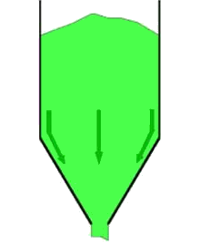

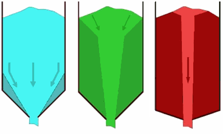
In both flow types, irregularities during flow can lead to shocks. Although there are various causes, the mechanism is basically the same.
There are or there will be stagnant areas in the bulk material that suddenly do start moving and then come to an equally sudden stop again.
Causes of vibrations and shocksThe phenomena referred to here should not be confused with the sudden collapse of semi-stable vaults or bridges as can occur in silo storage of cohesive materials, and which often causes significant damage immediately. We are talking about more or less periodic phenomena that occur with usually free-flowing products that are quite hard and have not too high internal friction. Well-known examples are maize, cement clinker, coal, iron ore, and various hard plastic granules.
From practical experience, several situations are known that can lead to silo quaking:
1) Stick-slip
Stick-slip can occur when a relatively large difference exists between static and dynamic friction.
This can occur with both internal friction, and wall friction.
In this case, the bulk material does not shear or slide along a wall evenly.
But it starts moving with difficulty, then shoots through and is slowed down again, a constantly repeating mechanism.
This creates a jerky pattern of movement that can lead to vibrations or shocks when interacting with the wall, and depending on the stiffness of the structure.

The occurrence of stick-slip also often turns out to be pressure-dependent: at higher pressure, the effect is (much) greater. This means that when the pressure is reduced, the degree of stick-slip decreases and sometimes even disappears completely. 2) Reversal of mass and core flow
In a storage situation where the flow pattern in the silo and product is in the transition region between mass and core flow, a situation as outlined in the figure may occur.
3) Shifting mass in core flow silos
A fairly steep flow channel can be formed in a core flow silo, as sketched in the figure opposite.
This flow channel is normally always refilled as bulk material flows in from the top of the stagnant zones.
4) In the case of malfunctioning feeders
In properly functioning mass flow silos, all the bulk material is in motion and no stagnant zones exist.
However, it regularly occurs in practice that a feeder installed below the discharge opening disrupts this ideal pattern. This is the case, for example, when a poorly designed discharge screw, vibrating feeder or discharge conveyor extracts the bulk material only over part of the discharge opening.
5) Shocks due to dilation during flow
Even in silos in which mass flow occurs, shocks can still occur. Because often the entire mass in the silo is involved, these shocks can be very large. The phenomenon can be explained as follows. In the vertical part of the silo, with sufficient filling degree, the bulk material sinks as a more or less solid block, the so-called plug-flow. In the hopper, movement must take place in the bulk product itself, which means that dilatation of the product must occur. This dilation starts at the outlet opening and extends upwards in the hopper. As a result, the bulk product in the cylinder, the plug, will experience less support from the dilated part in the hopper. As a result, it suddenly shoots down a bit after which it is slowed down again by the bulk material in the hopper, resulting in a shock. Also, the bulk material in the hopper is compacted again where the process starts again and another shock may occur. The size of the shock here is determined by the bulk material properties, by the space given to the bulk material to sink and the amount of mass in the plug involved. Combination of causesThe above phenomena sometimes also occur in combination. For instance, in core flow silos where the upper part of the product still sinks like a plug, the same shocks can occur as in mass flow silos. The occurrence of stick-slip can also sometimes initiate or amplify shock behaviour. The following will discuss in more detail options that exist to prevent or solve the problems described here. Possible solutions for shocking silosPrevention is better than cureThe contribution above described how and why vibrations, shocks and other undesirable phenomena can occur in a silo. We will now elaborate a little further on possible consequences of these problems and, more importantly, how they can be prevented or solved. Problems caused by shaking silosIn the case of silo singing or light vibrations, the consequences are usually not major. At most, it is irritating to operating personnel in the silo building and immediately around it. The same applies to 'honking', although this has occasionally led to complaints of neighbourly noise and the need to adjust usage patterns. It becomes more serious when the vibrations are such that parts of the structure vibrate along with it so that damage can occur. In the case of silo quaking, the matter certainly needs to be considered seriously. It not only leads to an undesirable situation for the operating personnel, but can also cause disruption of measuring equipment, or make dosing from the silo irregular because the dispensed product does not have a constant density. Severe impacts may even damage the silo or its supporting structure. It is notable that standards prescribing the calculation of silo loads pay little attention to this potential load increase. In the design phase of the silo
Already during the design phase, the issues mentioned here should be addressed. It should be avoided that the design results just on the boundary of mass and core flow, as this often gives rise to shocks due to unstable dead zones. It is better to sit well within the mass flow area, or if this is not possible or desired, to opt clearly for core flow . When using wedge-shaped hoppers with elongated discharge openings, the chosen extraction equipment should be designed to extract bulk material along the entire length of the opening. This is to avoid dead zones above part of the opening.
Modifying existing situations
In the design phase, the occurrence of shocks and vibrations can to some extent be investigated and then avoided. But the occurrence of shocks also remains unpredictable to a certain extent. It may also turn out that the bulk material does behave differently from what was assumed in the design phase, or because completely different products are stored in the silo. The question is then how to solve the problem of shock or vibration. The contribution above described that there may be several causes underlying the problem. First step towards a solution is therefore to identify which causes play a role in the situation at hand. On that basis, a solution can be sought.
Stick-slip vibrations
When stick-slip flow occurs in a silo, it is usually evidenced by slight vibrations felt at the cylinder wall. This need not be a problem unless the vibrations interfere with weighing or measurement, for example. Vibrations can also cause shocks at higher fill rates. To resolve this, it is necessary to determine whether stick-slip behaviour of bulk material occurs along the wall or internally.
This can be determined with a shear test, for example with the Jenike shear cell.
.
Oplossen van schokken bij een grensontwerp
When a fairly regular pattern of not too severe shocks occurs, it may be due to a boundary design, where the flow oscillates somewhat between mass and core flow.
This can be checked by measuring the wall friction, and determining whether it, in combination with the funnel angle, is at the boundary area.
If a boundary situation exists in a given case, as indicated in the figure as point A in axial-symmetric flow (left graph),
an attempt should be made to arrive at true mass flow. Several possibilities exist for this.

In situation with round or square hoppers and thus axially-symmetric flow, there is another possibility: switching to plane-symmetric flow.
This type of flow requires a less steep hopper angle to get mass flow, see point A in the graph of the plane-symmetric situation.
Resolving shocks at core flowIf core flow is found to occur, initial attempts can be made to obtain mass flow in one of the ways described above in situation where flow is at the boundary. However, in practical situations with core flow, the funnel angle is not nearly steep enough, or the wall friction is so high, that there are no easily practical solutions. One can still try to improve the flow behavior by vibrators on the funnel or blowing in air. But for real core flow, the chance of success is small because the flow is relatively far from the wall. However, when real shocks occur, it is sometimes possible to use air cannons to move the stationary zones at regular intervals. This does not completely prevent the shocks but will make them more regular and less violent. Resolving shocks at mass flowVibrations and shocks can also occur in a siutation with mass flow. These can be caused by a malfunctioning drawdown mechanism in which unstable areas above the outlet are created. The system should be checked for this and the extraction mechanism adjusted. However, shock problems can occur even with properly functioning discharge devices. Usually, with smaller filling of the silo, the intensity of the shocks appears to become less. In that case, it may be useful to reduce the pressure on the hopper. See silo pressure reduction options.. |

